YOUR GUIDE TO WIRING AND CONNECTION OF SOLAR PANELS

CONNECTION METHODS
A typical commercially available photovoltaic panel is rated between 50 and 300 watt. Given the fact a typical household needs several kilowatt, a single panel obviously is not enough for an entire house. To increase net power level multiple modules are connected into arrays. There are three main wiring configurations (see the diagrams below):
- Series
- Parallel
- Series/Parallel
To wire the panels in series you connect the positive terminal of one device to the negative terminal of the next one.
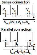
To wire the panels in parallel you connect together the terminals of the same polarity. With such connection the resulting output voltage stays the same as with a single module, and amperage adds.
With series/parallel connection, two or mores series strings are paralleled. In such a scheme both voltage and current increase. Assuming all modules are identical and receive exactly the same amount of sunlight:
Vout ≈ n×V
Iout ≈ m×I,
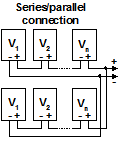
where V and I - voltage and current of each individual module respectively, n - number of modules in each series string; m - number of paralleled groups.
These diagrams of course are simplified. The strings are usually merged in a combiner box. Ideally, each circuit is fused separately. However, if you properly sized the conductors, you can protect several (probably up to three) circuits by a single fuse. Also, in practice, with series scheme the modules are often connected to diodes to protect shaded cells from a damage.
MAIN WIRING CODES AND STANDARDS
The main generic document in U.S. that governs most electrical installations is National Electric Code® (NEC®). It used to be updated every three years by National Fire Protection Association (NFPA®). The latest edition is NEC® 2017. Although technically this document is purely advisory, it is utilized nationwide as a de-facto standard. Nevertheless, the local authority that are enforcing the code, may always waive specific requirements, allow alternative installation methods, or conversely make the rules more severe. Therefore you should always check with the local codes.
Wiring of solar energy systems is covered by Article 690 of NEC® 2017. There are other applicable articles, such as 110, 250, 300, 310, 480, and 702. An installer and/or contractor should consult with these documents for all design decisions. Here is a quick checklist of some important facts, most of which are not so trivial.
- PV circuits shall not be run in the same cables or raceways with non-PV systems unless they are separated by a partition.
- PV wires should be identified and grouped, particularly you have to group separately DC and AC lines.
- DC buses from grounded panels must be protected with a DC ground fault interrupter.
- Solar panel voltage increases at lower temperatures. Therefore in order to determine voltage rating of the cables, disconnects and other equipment, you have to consider open circuit voltage of the arrays at the lowest possible ambient temperature in your area. Depending on your location, the correction factor can be up to 1.25.
- When you size circuits for their current rating, you need to find maximum short circuit current depending on your connection scheme (see diagrams above) and multiply it by 1.25 (i.e. add 25% margin). Note that the cells produce more current the colder they get. Given the fact that Isc is stated at 25oC, you need to add another current correction factor based on coldest possible operating temperature expected. This factor can be up to 1.25. As the result, the conductors have to be sized for up to 1.25×1.25=1.56×Isc.
- If DC bus voltage in house wiring exceeds 80V, you need to install a DC arc-fault circuit interrupter.
- DC conductors should have a disconnect switch or a circuit breaker.
- Wires in accessible places with voltages above 30V and all wires inside home should be run in raceways.
- Beneath the roof the cables should not be closer than 25 cm (10") to the roof decking.
- If you have more than 50V coming out of the PV system, generally, one of the DC buses have to be properly grounded in a single point as close as possible to the panels. However, the transformerless systems can be exempt from this requirement if they comply with NFPA 70® 690.35.
- Regardless of the voltage, metal frames of the solar panels and all equipment should be grounded.
- Generally, the DC voltage from PV can be up to 600V. However, if you use a system with battery backup, the battery bank's nominal voltage should be below 50V, unless exposed parts with higher voltages are not accessible during normal battery maintenance.
The information and suggestions here are provided AS IS for reference purpose only and do not constitute a professional or a legal advice. This is not an installation manual and is not intended to substitute or replace official codes and standards (see a complete legal disclaimer linked below).
NFPA 70®, National Electrical Code®, NEC® are registered trademarks of NFPA.